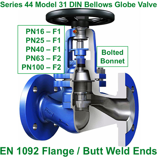
Globe valve BV25060 PN16
BVALVE Globe Valves include flanges designed according to EN 1092-2, face to face distance as per EN 558-1, ACME threaded stem screws and grounded shafts. Further premium characteristics include, safety stuffing box packing made of pure graphite. Body/bonnet compiled housed in tongue and grooved flanges. Besides, the plug has 360º free rotating configuration.
Steam Valves & Pneumatics
A steam valve is a mechanical device used to control the flow of steam in a piping system. It is typically installed in a steam line to regulate the amount of steam flowing through it. Steam valves can be used for a variety of purposes, including starting or stopping the steam flow, adjusting the flow rate, and controlling the pressure and temperature of the steam.
There are many types of steam valves, including globe, gate, ball, and butterfly valves. Each type of valve has its own unique design and operating characteristics and is suited for different applications and steam flow requirements.
Steam valves are an important component of many industrial processes that use steam as a heating or power source. They are used in a variety of industries, including power generation, chemical processing, oil and gas production, and food and beverage processing, among others. Proper selection, installation, and maintenance of steam valves is critical to ensure safe and efficient operation of the steam system.
Steam valves can be controlled using a variety of methods, depending on the specific application and system requirements. Here are some common ways to control steam valves:
Manual control: In this method, the valve is operated by a person who turns a handwheel or lever to open or close the valve. This is typically used in smaller systems where the flow rate and pressure are relatively low and there is not a high demand for precise control.
Pneumatic control: Pneumatic actuators use compressed air to open and close the valve. A control signal from a control system, such as a PLC, sends a signal to a valve positioner which then adjusts the air pressure to the actuator. This method is commonly used in industrial applications requiring fast response times and precise control.
Electric control: Electric actuators use an electric motor to turn the valve stem and control the flow of steam. They can be controlled by a variety of signals, such as analog signals or digital signals from a control system. Electric actuators are commonly used in process control systems where precise control is needed and where pneumatic systems are not feasible.
Hydraulic control: Hydraulic actuators use hydraulic fluid to operate the valve. A control signal from a control system adjusts the pressure of the hydraulic fluid to open or close the valve. This method is commonly used in large valves or high-pressure applications.
Here is a brief description of Air Filter Regulators, I/P Transducers and Valve Positioners and how they work in a steam valve application.
Air Filter Regulators play an important role in ensuring that actuators operate correctly. Air filter regulators regulate the air pressure that is used to operate pneumatic actuators. These units also offer protection from contamination by use of an integrated filter.
Air filter regulators work by reducing the pressure of compressed air from a higher supply pressure to a lower regulated pressure that is required for the pneumatic actuator to operate. The regulator typically consists of a diaphragm, a spring, and a valve that is controlled by the diaphragm. The regulator senses the pressure upstream of the valve and adjusts the valve position to maintain a consistent downstream pressure.
In steam valve applications, air filter regulators are used to ensure that the pneumatic actuators that control the steam valves operate at a consistent pressure, regardless of changes in the upstream air pressure. This allows for precise control of the steam flow rate or pressure, and ensures that the valve operates reliably and safely.
I/P (current-to-pressure) Transducers used in steam valve applications convert an electrical control signal from a controller into a pneumatic signal that can be used to control a pneumatic actuator.
Our Type 500-AC is one of the most common I/P transducers for the pneumatic control of your steam valve. The I/P transducer receives an electrical signal from the controller, which is typically a 4-20 mA current signal and modulates the pressure between 3 to 15 psi . The transducer converts this signal into a proportional pneumatic pressure signal, which is used to control the pneumatic actuator. As always, we recommend you protect these transducers with an air filter regulator.
In steam valve applications, the I/P transducer controls the position of a pneumatic actuator, which in turn controls the position of the steam valve. The position of the steam valve regulates the flow of steam through the system, allowing for precise control of steam flow rate or pressure.
I/P transducers are commonly used in steam valve applications because they offer a number of benefits, including fast and accurate response times, precise control of pressure or flow, and compatibility with a wide range of electrical control signals. They are also reliable and easy to maintain, making them a popular choice in industrial processes such as power generation, chemical processing, and manufacturing.
Valve Positioners like Type 2000 are devices used in steam valve control systems to precisely control the position of a valve’s stem, which in turn controls the flow of steam through the valve. Valve positioners are used to ensure that the valve opens and closes at the desired times, and to maintain a precise flow rate through the valve.
The basic operation of a valve positioner involves comparing the actual position of the valve with the desired position, and then adjusting the valve’s position as necessary to achieve the desired position. The valve positioner typically receives input from a controller that provides a setpoint for the valve position, based on the desired steam flow rate. The valve positioner then measures the actual position of the valve, usually using a feedback sensor such as a potentiometer, and compares it to the setpoint.
If the actual position of the valve is not the same as the setpoint, the valve positioner will send a signal to the actuator that controls the valve’s position, telling it to adjust the valve’s position accordingly. This feedback loop continues until the actual position of the valve matches the setpoint.
Overall, the method used to control a steam valve will depend on the system’s specific requirements, including the valve’s size, the pressure and temperature of the steam, and the need for precise control.
If you have any questions regarding your next application, don’t hesitate to contact our technical support team.

 Disc Type 1
  Disc Type 2
  Disc Type 3
  Disc Type 4
  Disc Type 5
  Disc Type 6
  Disc Type 7
  Disc Type 8
  Disc Type 9
  Disc Type 10
  Disc Type 11
  Disc Type 12